Canwin is a professional Power Transformer Company & Electrical Transformer Manufacturer
Language
Canwin is a professional Power Transformer Company & Electrical Transformer Manufacturer
The transformer is a static device in continuous operation, which is relatively reliable in operation and has less chance of failure. However, since most of the transformers are installed outdoors, and are affected by the load during operation and the short-circuit fault of the power system, various faults and abnormal situations inevitably occur during operation.
1. Common faults and abnormalities of transformers
Transformer faults can be divided into internal faults and external faults.
Internal faults refer to the faults that occur inside the case, including phase-to-phase short-circuit faults of windings, inter-turn short-circuit faults of one-phase windings, short-circuit faults between windings and iron cores, and disconnection faults of windings.
External faults refer to various phase-to-phase short-circuit faults between the external lead wires of the transformer, and single-phase ground faults that occur when the insulating bushing of the lead wires flashes through the box shell.
Transformer failure is very dangerous. Especially when an internal fault occurs, the high-temperature arc generated by the short-circuit current will not only burn out the insulation and iron core of the transformer winding, but also cause the transformer oil to decompose and produce a large amount of gas, causing deformation or even explosion of the transformer shell. Therefore, it must be cut off when the transformer fails.
The abnormal conditions of the transformer mainly include overload, lower oil level, overcurrent caused by external short circuit, high oil temperature of the transformer in operation, high winding temperature, high transformer pressure, and cooling system failure. When the transformer is in an abnormal operating state, an alarm signal should be given.
2. Configuration of transformer protection
Main protection for short-circuit faults: mainly longitudinal differential protection, heavy gas protection, etc.
Backup protection for short-circuit faults: mainly composite voltage blocking over-current protection, zero-sequence (direction) over-current protection, low-impedance protection, etc.
Abnormal operation protection: mainly includes overload protection, over-excitation protection, light gas protection, neutral point gap protection, temperature oil level and cooling system failure protection, etc.
3. Non-electricity protection
Transformer protection using non-electrical quantities such as oil, gas, and temperature of the transformer is called non-electrical protection. Mainly include gas protection, pressure protection, temperature protection, oil level protection and cooler full stop protection. The non-electricity protection acts on tripping or sending a letter according to the needs of the site.
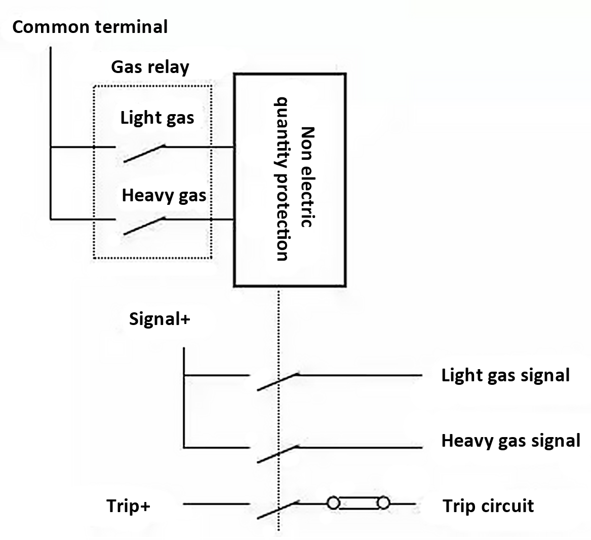
(1) Gas protection
When a fault occurs inside the transformer, due to the action of short-circuit current and arc at the short-circuit point, a large amount of gas will be generated inside the transformer, and the oil flow speed of the transformer will be accelerated. The protection realized by using gas and oil flow is called gas protection.
Light gas protection: When a slight fault or abnormality occurs inside the transformer, the fault point is partially overheated, causing part of the oil to expand, the gas in the oil forms bubbles and enters the gas relay, and the light gas protection operates to send out a light gas signal.
Heavy gas protection: When a serious fault occurs in the transformer oil tank, the fault current is large, and the arc causes a large amount of transformer oil to decompose, generating a large amount of gas and oil flow. The impact baffle makes the heavy gas relay protection act, sends out a heavy gas signal and trips the outlet. Remove the transformer.
The heavy gas protection is the main protection for internal faults of the oil tank, and it can reflect various faults inside the transformer. When a small number of inter-turn short circuits occur in the transformer, although the fault current is large, the differential current generated in the differential protection may not be large, and the differential protection may refuse to operate. Therefore, for the internal fault of the transformer, it is necessary to rely on heavy gas protection to remove the fault.
(2) Pressure protection
The pressure protection is also the main protection against internal faults in the transformer tank. Contains pressure relief and pressure sudden change protection, used to respond to the pressure of transformer oil.
(3) Temperature and oil level protection
When the temperature of the transformer rises to the warning value, the temperature protection will send out an alarm signal, and start the standby cooler.
When the transformer oil leaks or the oil level drops due to other reasons, the oil level protection will act and send out an alarm signal.
(4) Cooler full stop protection
When the transformer cooler in operation is completely stopped, the temperature of the transformer will rise. If it is not handled in time, it may cause damage to the insulation of the transformer winding. Therefore, when the cooler is completely stopped during the operation of the transformer, the protection will send out an alarm signal and cut off the transformer after a long delay.
4. Differential protection
Transformer differential protection is the main protection of the electrical quantity of the transformer, and its protection range is the part surrounded by the current transformers on each side. When faults such as phase-to-phase short-circuit and inter-turn short-circuit of the winding occur within this range, the differential protection must operate.
Regarding the principle of transformer differential protection, we have discussed in detail before, friends who need it can review the relevant content in historical records 6, 7, and 8. I won't go into details about this, and here I will simply add some concepts about the excitation inrush current.
(1) Excitation inrush current of transformer
The excitation current generated when the transformer is air-dropped is called the excitation inrush current. The magnitude of the inrush current is related to the structure of the transformer, closing angle, capacity, residual magnetism before closing and other factors. The measurement shows that when the transformer is air-dropped, the excitation inrush current due to the saturation of the iron core is very large, usually 2 to 6 times the rated current, and the maximum can be more than 8 times. Since the excitation inrush current only flows into the transformer on the charging side, a large differential current will be generated in the differential circuit, resulting in a malfunction of the differential protection.
The excitation inrush current has the following characteristics: a. The value of the inrush current is very large and contains obvious non-periodic components; b. The waveform is pointed and intermittent; c. It contains obvious high-order harmonic components, especially the second harmonic component. Obviously; d, the excitation inrush current is attenuated.
According to the above characteristics of the inrush current, in order to prevent the maloperation of the transformer differential protection caused by the inrush current, three principles are used in the project: high second harmonic content, asymmetric waveform, and large waveform discontinuity angle to realize the blocking of differential protection.
(2) Second harmonic braking principle
The essence of the second harmonic braking is to use the second harmonic component in the differential current to judge whether the differential current is a fault current or an exciting inrush current. When the percentage of the second harmonic component and the fundamental wave component is greater than a certain value (usually 20%), it is judged that the differential current is caused by the excitation inrush current, and the differential protection is blocked.
Therefore, the larger the second harmonic braking ratio is, the more the second harmonic current contained in the fundamental wave is allowed, and the braking effect will be worse.
(3) Differential quick break protection
When a serious fault occurs inside the transformer and the CT is saturated due to a large fault current, the secondary current of the CT also contains a large number of harmonic components. According to the above description, this is likely to cause differential protection due to the second harmonic braking. Block or delay action. This will severely damage the transformer. In order to solve this problem, differential quick-break protection is usually set.
The differential quick-break element is actually a high-value differential element for longitudinal differential protection. Different from general differential elements, it reflects the effective value of differential current. Regardless of the waveform of the differential current and the magnitude of the harmonic component, as long as the effective value of the differential current exceeds the setting value of the differential quick break (usually higher than the setting value of the differential protection), it will immediately act to cut off the transformer without excitation. Blocking of criteria such as inrush current.
The following introduces the backup protection of the transformer
There are many types of backup protection configurations for transformers. This issue mainly introduces two types of backup protections: complex voltage blocking overcurrent protection and grounding protection for transformers.
1. Overcurrent protection for complex pressure lockout
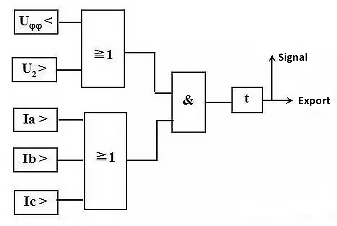
The complex voltage blocking overcurrent protection is the backup protection for large and medium-sized transformer phase-to-phase short-circuit faults. It is suitable for step-up transformers, system contact transformers and step-down transformers whose overcurrent protection cannot meet the sensitivity requirements. The composite voltage composed of negative sequence voltage and low voltage can reflect various faults within the protection range, which reduces the setting value of overcurrent protection and improves sensitivity.
Composite voltage overcurrent protection is composed of composite voltage element, overcurrent element and time element. The input current of the protection is the secondary three-phase current of the CT on the transformer's own side, and the input voltage is the secondary three-phase voltage of the PT on the transformer's own side or other sides. For microcomputer protection, the voltage of this side can be provided to other sides through software, so as to ensure that the overcurrent protection of any side can still be used when the PT on any side is overhauled. The action logic is shown in the figure below.
2. Grounding protection of the transformer
The backup protection for grounding short-circuit faults of large and medium-sized transformers usually includes: zero-sequence overcurrent protection, zero-sequence overvoltage protection, gap protection, etc. The following is a brief introduction based on three different grounding methods of the neutral point.
(1) The neutral point is directly grounded
For transformers with a voltage of 110kV and above whose neutral point is directly grounded, zero-sequence current protection that responds to ground faults should be installed on the side of the large-current grounding system. For transformers that are directly grounded on both high and medium sides, the zero-sequence current protection should have a direction, and the direction should point to the bus bars on each side.
The principle of zero-sequence current protection is similar to that of line zero-sequence protection, please refer to Issue 30. The zero-sequence current can be taken from the secondary current of the neutral point CT, or it can be self-generated by the secondary three-phase current of the CT on the local side. The zero-sequence voltage connected to the directional element can be taken from the open triangle voltage of the PT on the local side, or it can be self-generated by the secondary three-phase voltage on the local side. In the microcomputer protection device, the self-produced method is mainly adopted.
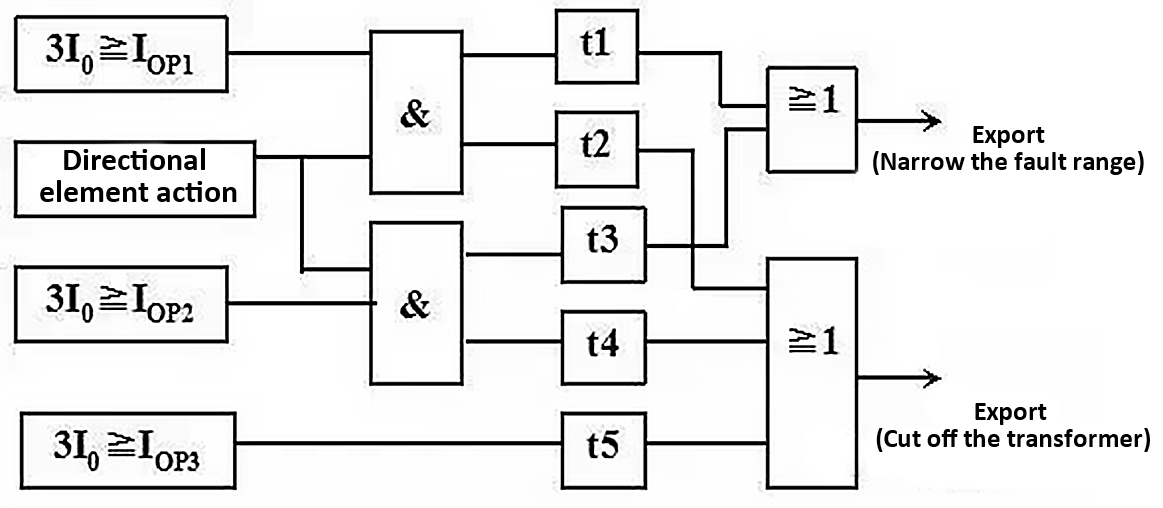
For large three-winding transformers, three-stage zero-sequence current protection can be used. Among them, Section I and Section II have directions, and Section III has no directions. There are generally two levels of delay in each section, and the fault range is narrowed with a short delay (jumping the bus coupler or the switch on the main side of the bar), and the transformer is cut off with a long delay (jumping the three-side switch). The specific protection configuration is determined according to the actual situation.
As shown in the figure, after the I or II section of the zero-sequence directional current protection operates, first jump the bus coupler or the switch on this side after a short delay t1 or t3 to reduce the scope of the fault. If the fault is still there, after a longer time Delay t2 or t4 jump the three-side switch to cut off the transformer. Section III has no direction, and the transformer is cut off directly after a delay.
(2) The neutral point is not grounded
The zero-sequence current passes through the neutral point of the transformer to form a zero-sequence circuit. However, if the neutral points of all transformers are grounded, the short-circuit current at the grounding point will be shunted to each transformer, which will reduce the sensitivity of zero-sequence overcurrent protection. Therefore, in order to limit the zero-sequence current within a certain range, there are regulations on the number of transformers that operate with the neutral point grounded.
For transformers that operate without grounding, zero-sequence voltage protection should be configured to prevent overvoltage damage to the transformer caused by gap arcs at fault points during ground faults.
Due to the high insulation level of the neutral point of the fully insulated transformer, when a ground fault occurs in the system, the zero-sequence current protection will first cut off the transformer with the neutral point grounded, and if the fault still exists, there will be zero-sequence voltage protection to cut off the neutral point without grounding the transformer.
(3) The neutral point is grounded through the discharge gap
Ultra-high voltage transformers are all semi-insulated transformers, and the insulation of the neutral point coil to the ground is weaker than that of other parts. Neutral point insulation is prone to breakdown. Therefore, gap protection needs to be configured.
The function of the gap protection is to protect the insulation safety of the neutral point of the neutral point ungrounded transformer.
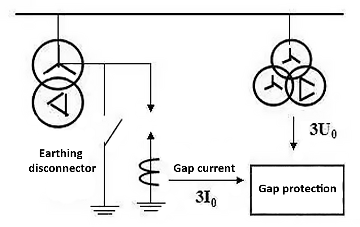
Install a breakdown gap between the neutral point of the transformer and the ground as shown in the figure. When the grounding isolating switch is closed, the transformer is directly grounded and zero-sequence overcurrent protection is put into use. When the grounding isolation switch is disconnected, the transformer is grounded through the gap and put into gap protection.
Gap protection is realized by using the gap current 3I0 flowing through the neutral point of the transformer and the bus PT opening triangle voltage 3U0 as criteria.
If the neutral point is raised due to a fault, the gap breaks down and a large gap current 3I0 is generated. At this time, the gap protection operates and the transformer is cut off after a delay. In addition, when a grounding fault occurs in the system, the zero-sequence protection of the neutral point grounding transformer operates, and the neutral point grounding transformer is cut off first. After the system loses the grounding point, if the fault still exists, the open triangle voltage 3U0 of the bus PT will be very large, and the gap protection will also operate at this time.

