Canwin is a professional Power Transformer Company & Electrical Transformer Manufacturer
Language
Canwin is a professional Power Transformer Company & Electrical Transformer Manufacturer
Introduction
transformer
A device that changes voltage, current, or phase by coupling a magnetic circuit
Why learn Transformers?
Transformers are also known as stationary AC motors
5.1 The basic working principle and structure of the transformer
5.1.1 The basic working principle of the transformer
Transformer has DC blocking effect
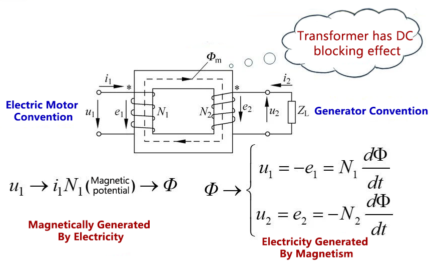
If the main magnetic flux changes according to the sine law, that is, φ(t)=φ.sinot, then each physical
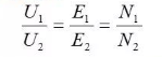
The effective value of the quantity satisfies the following relationship:
Ignoring the winding resistance and core loss, the primary and secondary powers are conserved, as follows:
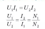
thus have
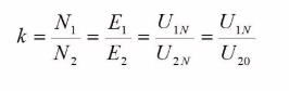
The turns ratio or turns ratio of the transformer,
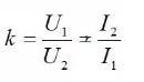
say is the apparent capacity.
It can be seen that the transformer realizes current conversion while realizing voltage transformation. also,
The transformer can also realize the function of impedance transformation.
The load impedance on the secondary side is:

If you look at the ZI from the primary side, its size is:
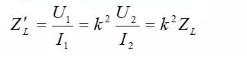
The structure of a single-phase transformer
1- Core column 2- Iron yoke 3- - High voltage winding 4- ~ Low voltage winding
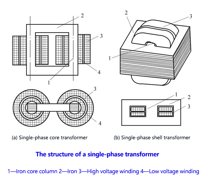
The structure of a three-phase transformer
Taps for high voltage windings of three-phase transformers
1-Iron core column 2-Iron yoke
3- low voltage winding 4- - high voltage winding
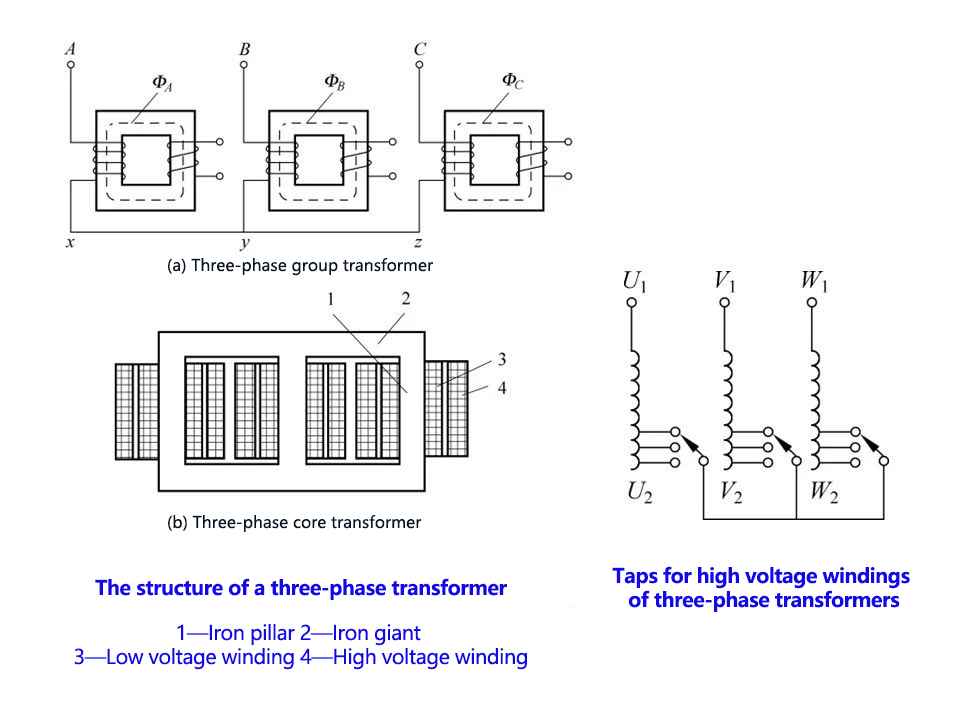
1- Nameplate 2- Thermometer 3- Moisture absorber 4- Oil level gauge 5- Oil conservator 6- Safety air passage 7- Gas relay 8- High pressure oil pipe
9 low pressure oil pipe 10 - tap switch 11 - fuel tank core 12 - oil drain valve 13 - coil 14 - ground plate 15 - - trolley
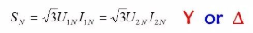
5.2 Transformer ratings
➢ Rated capacity or apparent capacity Sn;
➢Rated voltage Un
Rated current Iv;
➢Rated frequency fn;
➢Rated efficiency ηn ;
Both rated voltage and rated current refer to line value (ie line voltage or line current)
The following relationship exists between the rated data:
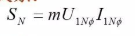
In the formula, m represents the number of phases of the transformer;
U1Nφ and I1Nφ represent the phase values of rated voltage and rated current, respectively.
For single-phase transformers:
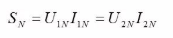
For three-phase transformers:
5.3 Analysis of no-load operation of transformers
definition:
The no-load of the transformer refers to the operating state in which the primary winding is applied with AC voltage and the secondary winding is open, that is, the secondary side is open (ie, the current is zero).
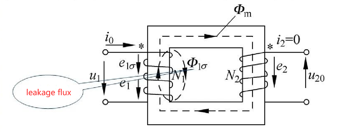
5.3.1 Electromagnetic relationship of transformers during no-load operation
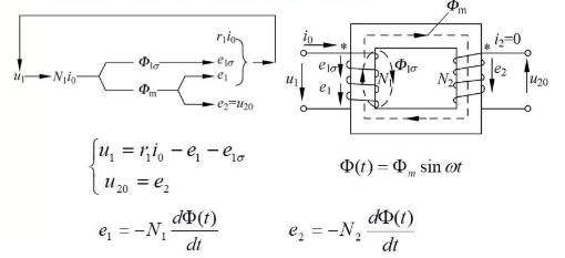
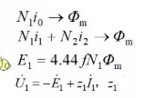
Written in phasor form as:
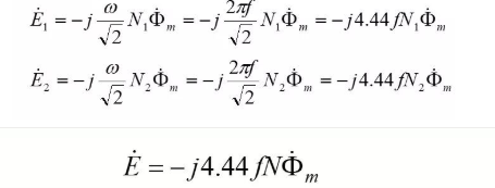
In conclusion:
The magnitude of the induced potential in the winding is proportional to the frequency, the number of winding turns and the amplitude of the magnetic flux; in phase, the induced potential in the transformer winding lags behind the main magnetic flux .
When the rated voltage is applied to the primary winding, the open-circuit voltage of the secondary winding is specified as the rated voltage of the secondary side, namely in this way, the transformation ratio of the transformer can be obtained as:
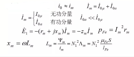
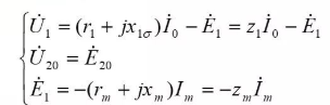
5.3.2 Equivalent of electrical parameters of magnetic circuit
The basic idea:
The magnetic circuit problem involved in the transformer is converted into a circuit problem, and then the transformer is calculated according to the unified circuit theory.
For leakage flux:
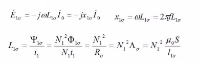
Then X1δ or L1δ, can be used to reflect the leakage magnetic circuit. (as a constant, why?)
For main flux:
First, the concept of equivalent sine wave current is introduced, and the non-sinusoidal no-load current is replaced by equivalent sine wave current.
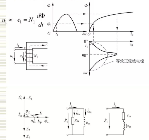
(a) Phasor diagram (b) Equivalent circuit (c) Equivalent circuit
for an ideal transformer:
5.3.3 The no-load voltage balance equation, phasor diagram and equivalent circuit diagram of the transformer
In conclusion:
The power factor of the primary side is lower when the transformer is running at no load. therefore,
Transformers generally do not allow no-load or light-load operation.
5.4 Analysis of the load operation of the transformer
After the transformer is loaded, the current on the secondary side is no longer zero, resulting in changes in the electromagnetic process inside the core.

5.4.1 The balance equation of the magnetic potential when the transformer is under load
5.4.1 The balance equation of the magnetic potential when the transformer is under load
No-load/load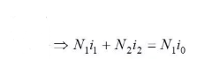
The above formula can be understood as: As the load current increases, the corresponding magnetic potential (or current) must be increased on the primary side to offset the secondary side magnetic potential, so as to maintain the magnetic flux or magnetic potential unchanged at no-load. So there are:
In conclusion:
After the transformer is loaded, the primary side current increases. The greater the load (current) required on the secondary side, the greater the current supplied on the primary side. That is, the transformer can be regarded as a balance between supply and demand.
5.4.2 Equivalent electrical parameters of the secondary leakage magnetic circuit after the transformer is loaded
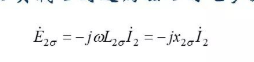
X₂δ or Ḯ₂can be used to reflect the situation of the secondary side leakage magnetic circuit.
5.4.3 Electromagnetic relationship when the transformer is under load
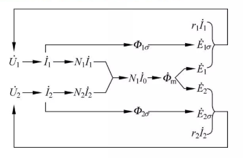
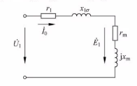
5.5 Basic equations, equivalent circuits and phasor diagrams of transformers
5.5.1 The basic equation of the transformer is equivalent to the various analyses and parameters in the previous section, and the phase
Transformer Basic Equations in Quantitative Form
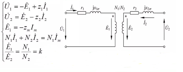
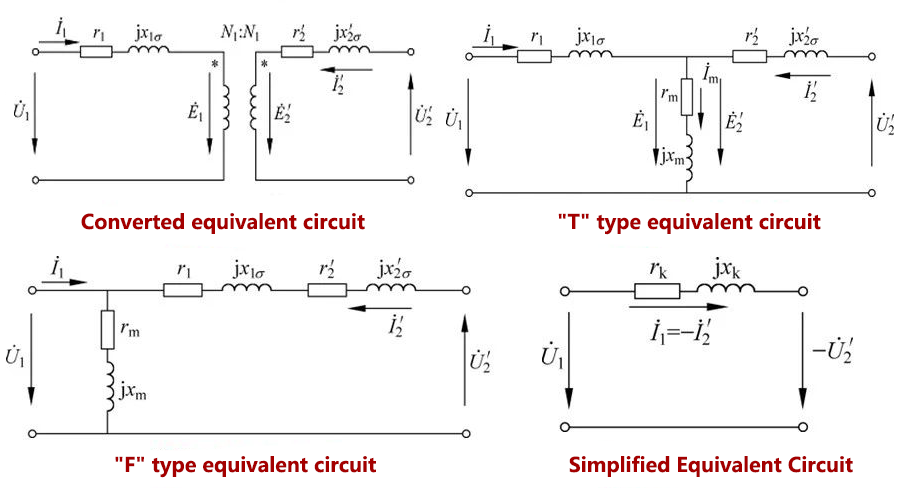
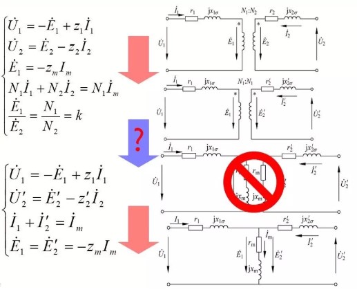
5.5.2 Equivalent circuit for transformer load operation
According to the previous basic equations, various analysis and calculations of the transformer can be performed, but the calculations are relatively cumbersome. In engineering, it is generally converted into an equivalent circuit to replace the actual transformer.
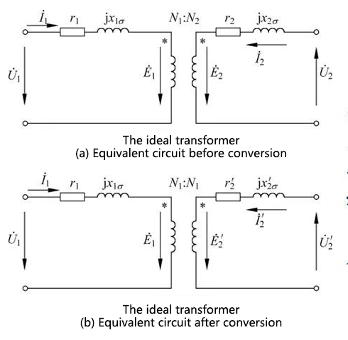
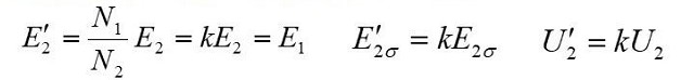
The primary and secondary sides of the equivalent circuit are electrically independent of each other. In order to simplify the calculation, the number of winding turns on the secondary side is usually increased from N to 1, so that each physical quantity on the secondary side will change accordingly. This process is also called conversion.
The principle of conversion:
Before and after conversion, the electromagnetic relationship should be kept unchanged, namely:
(1) The magnetic potential before and after conversion should remain unchanged;
(2) The electric power and loss before and after conversion should remain unchanged.
(1) Voltage conversion (convert E ₁the same as E₂)
(2) Current conversion (to ensure that the magnetic potential remains unchanged)
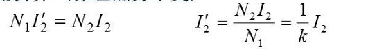
(3) Impedance conversion (to ensure that the energy transfer relationship remains unchanged, including active and reactive power)
Active Power 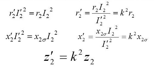
Reactive Power
5.5.3 The phasor diagram when the transformer is under load The phasor diagram not only shows the electromagnetic relationship of the transformer, but also can intuitively see the magnitude and phase relationship of each physical quantity in the transformer.
Assuming that the circuit parameters are known, and the size and phase of the load are given, the phasor diagram can be drawn according to several steps.
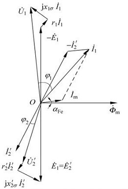
In conclusion:
After the transformer is loaded, the power factor angle of the primary side is reduced, and the power factor is improved.
5.6 Test and measurement of transformer equivalent circuit parameters The equivalent circuit can be used to analyze the operating performance of the transformer. First, the parameters in the equivalent circuit must be known.
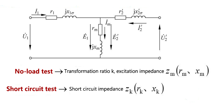
No-load test -> transformation ratio k, excitation impedance
Short circuit test → short circuit impedance
5.7 Calculation of steady-state operating characteristics of transformers
5.7.1 External characteristics and voltage change rate of transformers
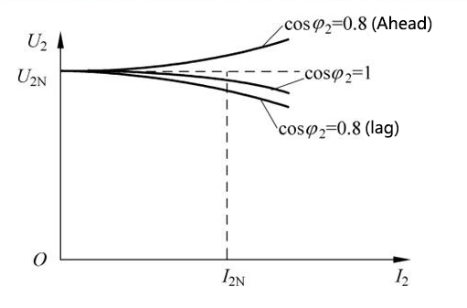
Definition of external characteristics (reflecting the quality of the power supply of the transformer to the load)
The relationship curve between the terminal voltage of the secondary side of the transformer and the load current of the secondary side under the conditions of rated power supply voltage and a certain load power factor.
Typical external characteristics of transformers under various loads
Definition of Voltage Rate of Change:
Under the condition of rated power supply voltage and certain load power factor, the percentage of secondary side terminal voltage change from no load to rated load, namely:
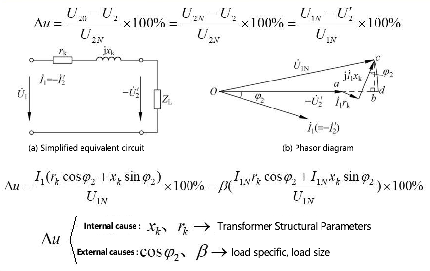
∆u
Internal factors: xᶄ, rᶄ → structural parameters of the transformer
External factors: cosφ2, β-→load specific, load size
Discussion: The transformer is generally rᶄ: much smaller than xᶄ please refer to Example (5-1)
◆For pure resistive load, cosφ2=1, sinφ2=0, so ∆u is small;
◆For inductive loads,
cosφ2>0, sinφ2>0, so ∆u>0,
that is, with the increase of the load current, the voltage on the secondary side decreases greatly;
◆For capacitive load, cosφ2>0, sinφ2<0, if |rᶄ cosφ2|<| xᶄ sinφ2|,Then ∆u<0,
indicating that with the increase of the load current I2, the voltage on the secondary side can be
can rise.
The application of capacitive load on the secondary terminal voltage of the transformer:
(1) Compensate reactive power, improve power factor, and reduce line loss
(2) Increase the power grid voltage of the factory to solve the problem of heavy factory load and power grid voltage drop
5.7.2 Efficiency characteristics of transformers.
The efficiency of a transformer is defined as:
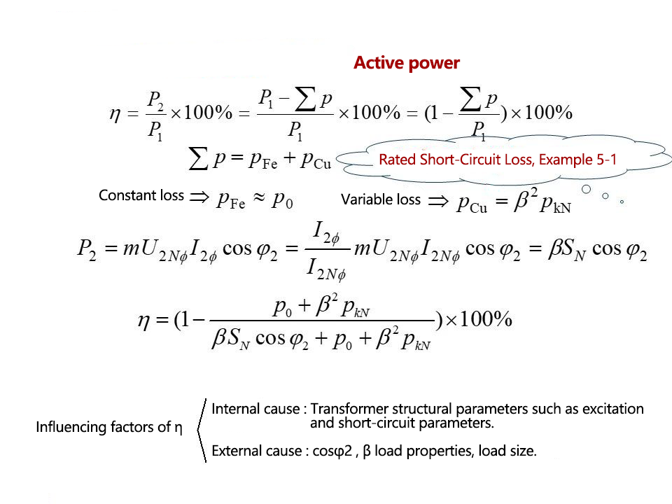
Influencing factors of η
Internal factors: transformer structural parameters such as excitation and short-circuit parameters
External factors: cosφ2, β load nature, load size
The efficiency characteristic is defined as:
Under the condition of rated voltage and a certain load power factor,
η= f(I2)
(orη = f(β) ).
The rated efficiency of the transformer is generally higher
Most of them are above 95%, and large transformers can reach 99%. The AC motor has a rotating part, the efficiency lower.
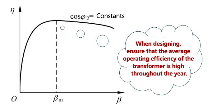
Solve for the maximum efficiency of the transformer:
5.8 Special Problems of Three-Phase Transformers
The previous chapters took a single-phase transformer as an example to study the basic equations, equivalent circuits and performance calculation methods of the transformer, which are also applicable to three-phase transformers.
Three-phase transformers also have their own special problems:
➢Connection method
➢Magnetic circuit structure
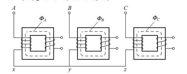
5.8.1 Connection method and connection group of three-phase transformer
(1) Connection method
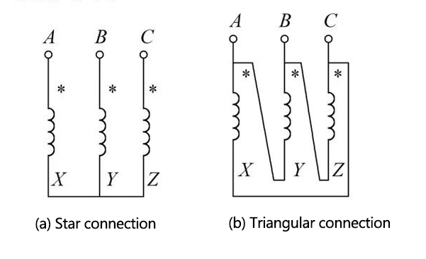
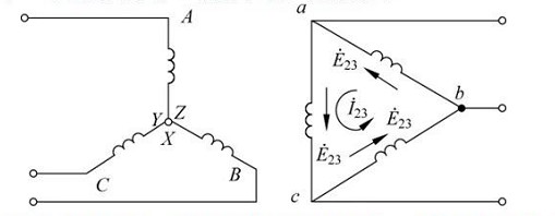
(a) star connection (b) delta connection
Regulation:
Capital letters (A, B, C, N) represent the original square;
lowercase letters (x, y, z,n) on behalf of the paying party;
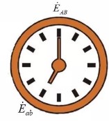
(2) Linking groups
In three-phase transformers, groups are usually used to represent the phase difference between the primary and secondary voltages of the three-phase transformer: θ=(EABEab), which is a multiple of 30°, exactly between the hours on the clock face Therefore, the phase relationship between the high and low voltage winding wire potentials of the three-phase transformer is generally expressed by "clock notation", that is, the group number.
How to determine the group:
Use the high-side line potential EAB as a long hand, pointing to the "12" low-side line potential on the clock face.
Eab is a short needle, and the number it points to is the connection group number of the three-phase transformer.
A. Connection group of single-phase transformer
The concept of the same name:
When the same iron core is wound with two coils, in order to reflect the two coils on the same iron core
The winding direction relationship between the coils usually introduces the concept of "same name end".
The same name side says:
Two coils on the same core are linked by the same magnetic flux. When the magnetic flux is alternating, if the instantaneous potential induced by one end of a coil is positive relative to the other end of the same coil, the two terminals that are both positive are It is the same name terminal, which is represented by "*",
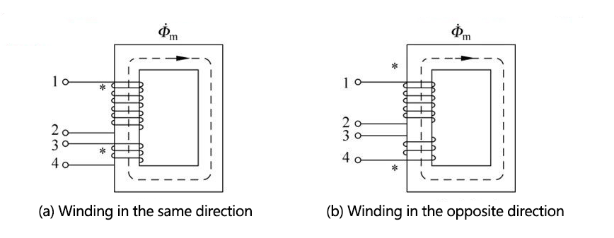
(a) Winding in the same direction (b) Winding in the opposite direction
For single-phase transformers, the head end of the high-voltage winding is marked A and the tail end is marked X; the head end of the low-voltage winding is marked a and the tail end is marked X.
Regulation:
The positive direction of the potential is from the head end to the tail end.
In the transformer, the end with the same name can be used as the head end, or the end with the same name can be used as the head end. Figures a and b below show the phase relationship between the primary and secondary potentials in these two cases, respectively.
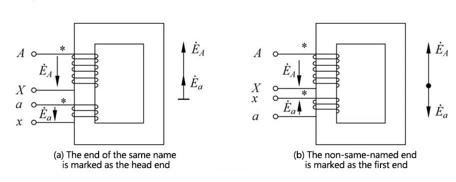
(a) The end with the same name is marked as the head end (b) The end with the same name is marked as the head end
If the identification method in which the end with the same name is marked as the head end is adopted (see Figure a), the group of single-phase transformers is I, i0; for I, i6.
B. Connection group of three-phase transformer
Through the phase relationship between the primary and secondary potentials of the single-phase transformer (or the primary and secondary phase potentials of the three-phase transformer), the phase relationship between the primary and secondary potentials of the three-phase transformer can be further determined, that is, the connection group.
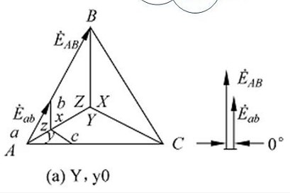
(1) Y/Y connection three-phase transformer

(2) Y/△ connection three-phase transformer
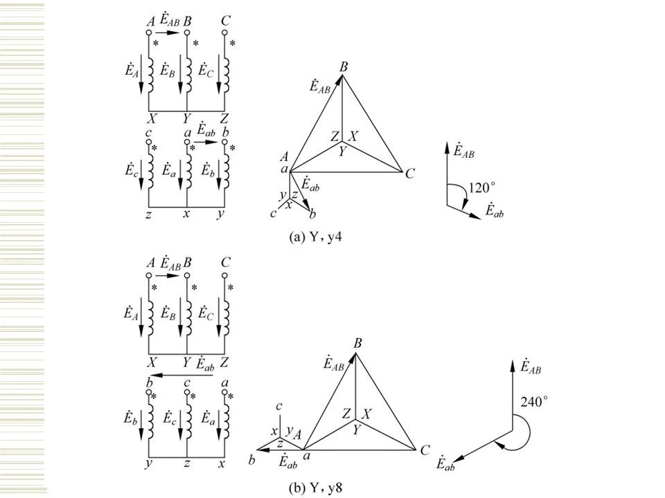
General steps to determine the three-phase transformer group:
(1) Draw the potential phasor diagram of the high-voltage side winding;
(2) Coincide point a and point A, and draw the phase potential of the low-voltage winding ax according to the phase relationship between the high and low-voltage windings on the same core column.
(3) According to the wiring method of the low-voltage winding, draw the potential phasor diagram of the other two phases of the low-voltage winding;
(4) Determine EB and E from the potential phasor diagrams of the high and low voltage windings. between
The phase relationship of the three-phase transformer is obtained, and the connection group number of the three-phase transformer is obtained.
Y/Y,△/△ an even group
Y/△,Y/△ an odd array
There are five commonly used standard join groups:
Y, yn0, Y, d11, YN, d11, YN, y0, Y, y0, the first three are the most commonly used.
5.8.2 Magnetic circuit structure of three-phase transformer
The characteristics of three-phase group transformers: the magnetic circuits of each phase are independent of each other.
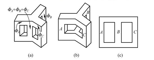
The characteristics of the three-phase core transformer: the magnetic circuits of each phase are related to each other.
5.8.3 Correct matching of winding connection and magnetic circuit structure of three-phase transformer
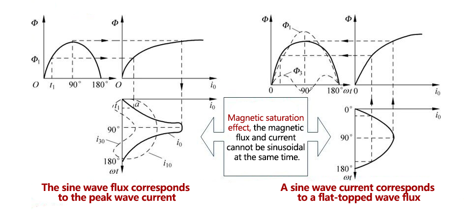
The sine wave flux corresponds to the peak wave current The sine wave current corresponds to the flat top wave flux
in conclusion:
In order to ensure that the phase potential waveform is sinusoidal, the main magnetic flux of each phase should change according to the sinusoidal law. At this time, it is required that the excitation current must be a peak wave, that is, the path of the third harmonic current must be ensured in the circuit connection. (why? )
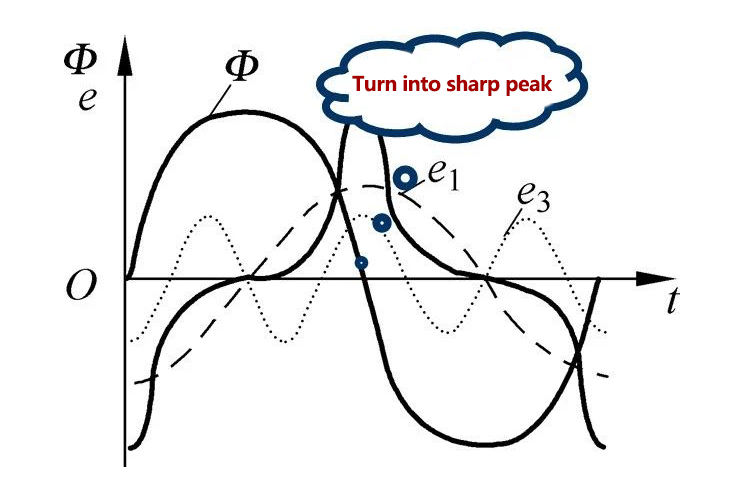
Flux of flat-top wave - (derivation) - the potential of the peak wave, if the peak is too large, it may break down the insulation of the winding.
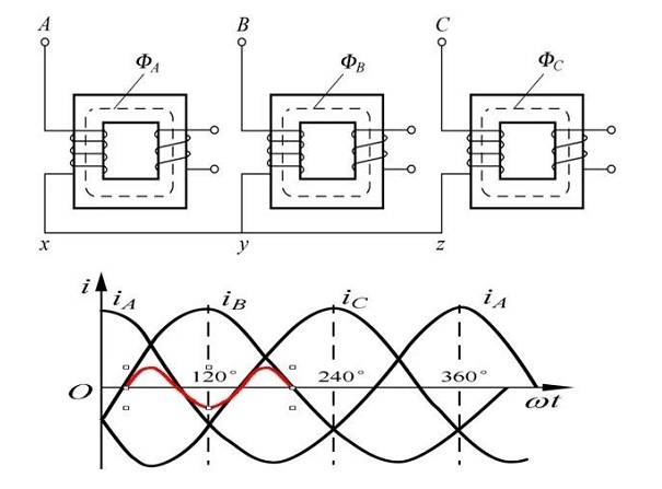
Considering that the magnetic circuits of each phase of the group transformer are independent of each other, they are not related to each other. The third harmonic magnetic flux contained in the main magnetic flux is the same as the fundamental wave magnetic flux, and circulates in the main magnetic circuit of each phase transformer, thereby inducing a higher amplitude third harmonic potential in the primary and secondary windings, resulting in The phase potential waveform is a sharp-topped wave (obtained by the derivation of the flat-topped wave magnetic flux). The peak of the peak wave phase potential may break down the winding insulation.
Considering that the magnetic circuits of each phase of the core transformer are related to each other, the phase of the third harmonic magnetic flux in the main magnetic flux of the three-phase flat top wave is the same, and it is impossible to circulate in the magnetic circuit of the main iron core. A closed magnetic circuit is formed, causing the third harmonic potential induced by the third harmonic magnetic flux in the primary and secondary windings to be small, and the phase potential waveform is still close to a sine wave.
in conclusion:
(1) The three-phase winding of the three-phase group structure transformer cannot be connected by Y/Y; .
(2) The three-phase winding of the transformer with three-phase core structure can be connected by Y/Y, but the capacity should not be too large.
One side of the winding is connected in a delta, and the third harmonic current has a path. Therefore, no matter whether the magnetic circuit is a group type or a core type structure, the three-phase windings can be connected by △/Y.
One side of the winding is Y-connected, and the third harmonic current cannot flow in it, but the third harmonic magnetic flux generated by the sine wave current will induce the third harmonic current in the secondary winding (delta connection) (see the figure below). ), it can also ensure that the main magnetic flux waveform is close to sinusoidal, so the induced phase potential is also sinusoidal. It can be seen that the effect of the triangular connection on the same primary side is similar.
in conclusion:
For 0/Y (or Y/0) connected three-phase windings, it can be used for three-phase transformers of group structure or three-phase transformers of group structure.
in conclusion:
In order to ensure that the phase potential is sinusoidal, it is best to use a delta connection on one side of the three-phase transformer.
5.9 Special transformers in electric drag systems
5.9.1 Autotransformers
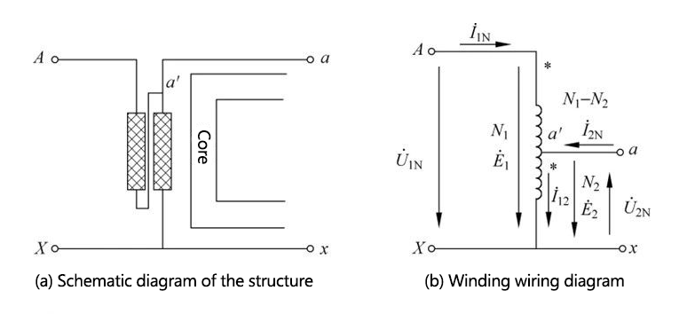
(a) Schematic diagram of the structure (b) Winding wiring diagram
Features: There is a common winding between the primary and secondary side windings, which leads to not only magnetic coupling but also electrical connection between the primary and secondary side windings.
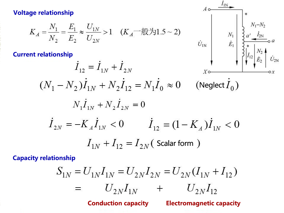
In conclusion:
The capacity of the autotransformer is made up of two parts:
(1) Electromagnetic power U2nIl2: it is the power transmitted to the load through the electromagnetic coupling between the winding Aa and the common winding ax;
(2) Conducted power U2nI1N: it is the electric power directly transmitted to the load through the common winding ax.
➢Electromagnetic capacity < rated capacity
Small size, low iron and copper consumption, high efficiency
➢Small ratio
The common part current is smaller than the secondary side rating
The gap is not obvious, the economy is reduced
➢There is a direct electrical connection, internal insulation and overvoltage protection need to be strengthened.
5.9.2 Transformer
Voltage transformer - measuring high voltage with low voltage meter
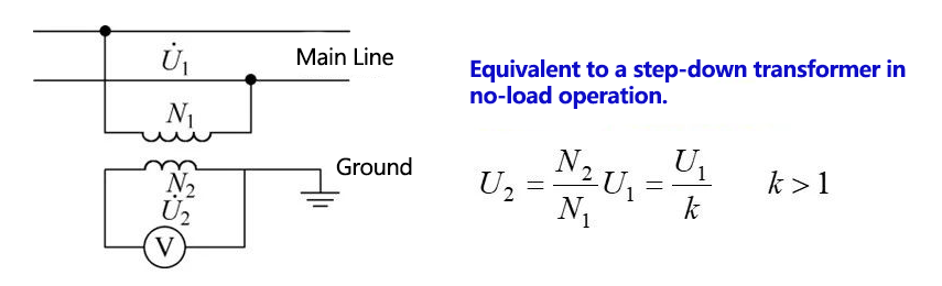
Precautions:
One end of the secondary side should be grounded; (to ensure safety and prevent the accumulation of static charge from affecting the reading)
The secondary side must not be short-circuited, otherwise the voltage transformer will be burned out. (It can increase the current if it can be stepped down)
Current Transformer 1 - Measure large current with low ammeter
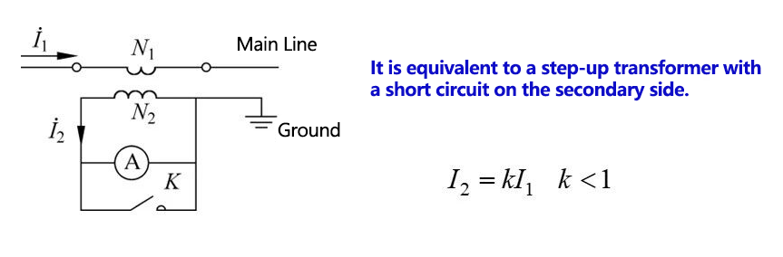
Precautions:
➢ One end of the secondary side should be grounded; (to ensure safety and prevent the accumulation of static charge from affecting the reading)
➢ The secondary side cannot be opened, otherwise a higher voltage spike will be induced on the secondary side due to the large number of turns on the secondary side, and the winding insulation of the transformer will be broken down. (The voltage can be boosted if the current can be lowered)

