The cooling system of the power transformer consists of two parts: the internal cooling system, which ensures that the heat of the winding and the iron core is dissipated into the surrounding medium; the external cooling system, which ensures that the heat in the medium is dissipated to the outside of the transformer. According to the size of the transformer capacity, the medium and the type of circulation, the transformer adopts different cooling methods.
1. Representation of cooling method
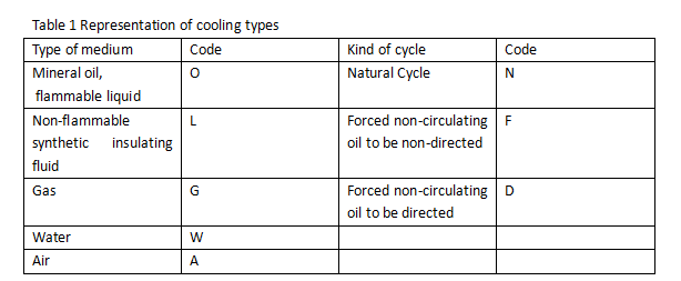
The cooling method of the transformer is generally represented by a combination of four codes, which are represented as follows from left to right:

For example: ONAN means oil-immersed self-cooling, that is, the internal oil is naturally circulated, and the external air is naturally circulated
Second, the cooling method of the transformer
The cooling method of oil-immersed power transformers, according to the size of its capacity, the cooling system can be divided into: oil-immersed self-cooling, oil-immersed air-cooled, forced oil circulation air-cooled, forced oil circulation water-cooled and so on.
1. Oil-immersed self-cooling
The oil-immersed self-cooling cooling system has no special cooling equipment, the oil circulates naturally in the transformer, and the heat from the iron core and windings is transferred to the tank wall or radiator by the convection of the oil. According to the size of the transformer capacity, it can be divided into three different structures:
1.1. Smooth box wall. The transformer with small capacity adopts this structure, the box shell is welded with steel plate, and the box wall is completely smooth;
1.2. Cooling rib type box wall. Weld some heat dissipation ribs on the smooth box wall to expand the area in contact with the air, which is suitable for transformers with slightly larger capacity;
1.3. Heat pipe or radiator cooling. For transformers with larger capacity, in order to increase the cooling surface of the fuel tank, several radiators are installed outside the fuel tank. The radiator is a set of heat dissipation pipes with upper and lower headers. Remove parts.
Figure 1 shows the oil flow path of an oil-immersed self-cooled transformer with heat pipes. When the transformer is running, the oil in the oil tank is heated due to the heating of the iron core and the winding, the hot oil will rise to the top of the oil tank, and then enter the heat dissipation pipe from the upper inlet of the heat dissipation pipe. Get cool. The cold oil descends in the radiating pipe, and then flows into the lower part of the transformer tank from the lower end of the pipe, and automatically circulates the oil flow, so that the transformer core and windings are effectively cooled.
The oil-immersed self-cooling cooling system has a simple structure and high reliability, and is widely used in transformers with a capacity of less than 10,000kVA.
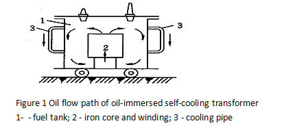
Figure 1 Oil flow path of oil-immersed self-cooling transformer
1- - fuel tank; 2 - iron core and winding; 3 - cooling pipe
2. Oil-immersed air-cooled
Oil-immersed air-cooled cooling system, also known as oil natural circulation, forced air-cooled cooling system. It is to install one or several fans beside each radiator of the transformer oil tank to change the natural convection of the air into forced convection to enhance the heat dissipation capacity of the radiator. Compared with the self-cooling system, the cooling effect can be increased by 150% to 200%, which is equivalent to a 20% to 40% increase in the output capacity of the transformer.
When the load is small, the fan can be stopped to make the transformer run in self-cooling mode. When the load exceeds a certain value, such as 70% of the rated load, the fan can be automatically put into operation. This cooling method is widely used in medium-capacity transformers above 10,000kVA.
3. Forced oil circulation air-cooled
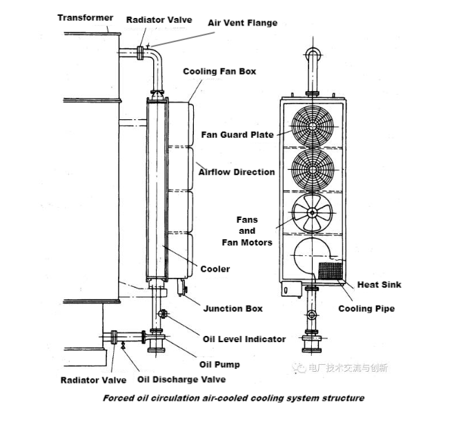
Forced oil circulation air-cooled cooling system for large capacity transformers. This cooling system is based on oil-immersed air-cooling, and a submersible oil pump is installed on the connecting pipe between the main casing of the fuel tank and the radiator with a fan (also called a cooler). When the oil pump is running, the oil in the forced oil tank is sucked into the radiator from the upper part, and then enters the oil tank from the lower part of the transformer to realize forced oil circulation. The cooling effect is related to the circulation speed of the oil. Figure 2 shows the cooling structure of the forced oil circulation air-cooled cooling system used in large transformers.
4. Forced oil circulation water cooling
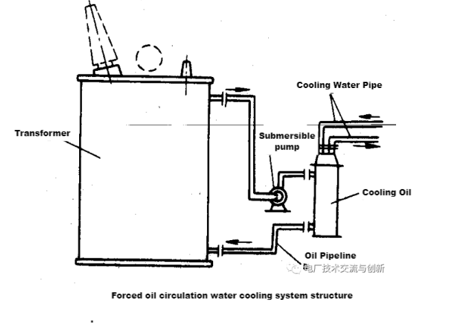
The forced oil circulation water cooling system consists of submersible oil pump, oil cooler, oil pipeline, cooling water pipeline, etc. When working, the oil on the upper part of the transformer is sucked by the oil pump and then pressurized. When the oil is forced to pass through the oil cooler, the cooling water is used to cool the oil. Therefore, in this cooling system, the heat of the iron core and the winding is first transferred to the oil, and then the heat in the oil is transferred to the cooling water. This cooling method works well, but the sealing requirements of the transformer are very high, and the oil pressure must be higher than the cooling water pressure during the cooling process. The forced oil circulation water-cooled cooling system structure is shown in Figure 3.
CONTACT US
Take advantage of our unrivaled knowledge and experience, we offer you the best customization service.



LEAVE A MESSAGE
Please fill out and submit the form below, we will contact you in 48 hours, thank you!
RECOMMENDED
They are all manufactured according to the strictest international standards. Our products have received favor from both domestic and foreign markets.