Canwin is a professional Power Transformer Company & Electrical Transformer Manufacturer
Language
Canwin is a professional Power Transformer Company & Electrical Transformer Manufacturer
Oil-immersed transformers have the characteristics of good heat dissipation, low loss, large capacity and low price. At present, most of the power transformers running on the grid are oil-immersed transformers, of which more than 80% are cooled by natural oil circulation. It is a commonly used cooling structure to set a guide plate in the coil of a natural oil circulation transformer. This paper focuses on analyzing the structure, operation and maintenance of oil-immersed power transformers, and specifically analyzes the oil system of oil-immersed power transformers, and briefly analyzes the faults of oil-immersed power transformers. Hope to increase understanding and analysis of my country's oil-immersed power transformers.
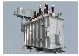
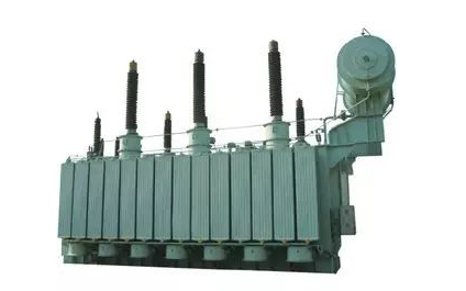
Oil-immersed transformer construction
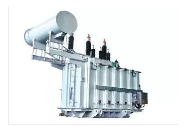
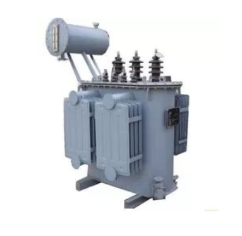
The core part of the three-phase oil-immersed transformer is composed of a closed iron core and a winding set on the iron core column. In addition, there are fuel tanks, oil conservators, casings, breathing apparatus, explosion-proof pipes, radiators, tap changers, gas relays, thermometers, oil purifiers, etc.
1) iron core
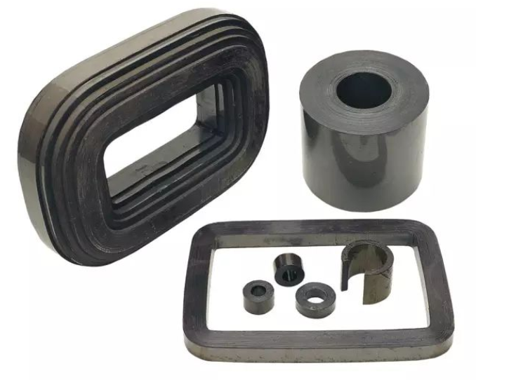
The iron core is the magnetic circuit part of the transformer. In order to reduce the magnetic hysteresis and eddy current loss in the iron core, the iron core is made of 0.35mm~0.5mm thick silicon steel sheets. According to the arrangement of the windings in the iron core, there are iron core type and iron shell type. The upright part of the iron core of the three-phase transformer is called the iron core column, and the low-voltage winding and the high-voltage winding of the transformer are covered on the column; the horizontal part is called the iron yoke, which is used to form a closed magnetic circuit.
In large-capacity transformers, in order to make the heat generated by the loss of the iron core fully taken away by the insulating oil during circulation, so as to achieve a good cooling effect, cooling oil passages are often provided in the iron core.
(2) Winding
The winding, also called the coil, is the circuit part of the transformer and is divided into primary and secondary windings. The winding connected to the power supply is called the primary winding, and the winding connected to the load is called the secondary winding. The primary and secondary windings are wound with copper or aluminum wires wrapped with high-strength insulation.
The primary and secondary windings of each phase of the three-phase transformer are made into a cylindrical shape and sleeved on the same iron core column, the low-voltage winding with a small number of turns is sleeved inside and close to the iron core, and the high-voltage winding with a large number of turns is sleeved outside the low-voltage winding. This placement is because it is easier for the low-voltage winding to insulate the core. A sleeve made of insulating material is used to isolate the low-voltage winding and the iron core and between the high-voltage winding and the low-voltage winding to insulate them reliably. In order to facilitate heat dissipation, a certain gap is left between the high and low windings as an oil passage, so that the transformer oil can flow.
The main faults of transformer windings are short-circuit between turns and short-circuit to the casing. Turn-to-turn short circuit is mainly due to insulation aging, or due to the overload of the transformer and the mechanical damage to the insulation during a traversing short circuit. The oil level in the transformer drops, so that when the winding is exposed to the oil level, an inter-turn short circuit can also occur; in addition, when there is a cross-circuit, the winding is deformed due to the overcurrent effect, and the insulation is mechanically damaged, and an inter-turn short circuit will also occur.
When shorted between turns, the current in the shorted winding may exceed the rated value, but the overall winding current may not exceed the rated value. In this case, the gas protection operates, and the differential protection device will also operate when the situation is serious.
The cause of short-circuit to the casing is also due to aging insulation or moisture in the oil, a drop in the oil level, or due to lightning and operating overvoltage. In addition, when a cross-circuit occurs, the winding is deformed due to overcurrent, and a short-circuit to the casing will also occur. When short-circuiting the casing, it is generally the action of the gas protection device and the action of the grounding protection.
(3) Fuel tank
The oil tank is the outer casing of the transformer, the iron core and windings are installed in it, and it is filled with transformer oil. For transformers with relatively large capacity, heat sinks or heat pipes are installed outside the tank. Oil leaks are a common problem with fuel tanks.
Transformer oil is a mineral oil with good insulating properties, which has two functions:
The first is insulation. The insulation performance of transformer oil is better than that of air. Immersion of windings in oil can improve the insulation performance of various places, and avoid contact with air to prevent windings from being damp;
The second is the heat dissipation effect, which uses the convection of the oil to dissipate the heat generated by the iron core and the winding to the outside through the box wall and the heat dissipation pipe. Transformer oil is divided into three specifications: No. 10, No. 25, and No. 45 according to its freezing point. Their freezing points are -10°C, -25°C, and -45°C, which are generally selected according to local climatic conditions.
(4) Oil conservator (oil pillow)
The oil conservator, commonly known as the oil pillow, is a cylindrical container placed horizontally above the oil tank and connected to the oil tank of the transformer with a pipeline. The volume of the oil conservator is generally about 10% of the oil tank volume. The oil conservator is a capsule type oil conservator, and the capsule isolates the oil in the oil conservator from the outside air. When the transformer oil is thermally expanded, the oil flows from the oil tank to the oil conservator; when the transformer oil shrinks, the oil flows from the oil conservator to the oil tank. The oil conservator has two functions: First, when the volume of transformer oil expands or shrinks with the change of oil temperature, the oil conservator acts as oil storage and replenishment, ensuring that the oil tank is filled with oil and the iron core and winding are soaked. In the oil; the second is to reduce the contact area between the oil surface and the air to prevent the transformer oil from being damp and deteriorated.
The oil level display of the oil conservator adopts a connecting rod type ferromagnetic oil level gauge to observe the oil level. The oil level gauge is engraved with the oil level standard line when the oil temperature is -30℃, +20℃ and +40℃, which is used as the oil filling standard. +40℃ on the oil level mark indicates the maximum oil level of the transformer in full-load operation when the highest ambient temperature of the installation site is +40℃, and the oil level should not exceed this line; +20℃ indicates the oil level when the annual average temperature is +20℃ during full-load operation Height; -30℃ means the minimum oil level line of the no-load transformer when the environment is -30℃, and should not be lower than this line. If the oil level is too low, add oil. The oil pillow is equipped with breathing holes, so that the upper space of the oil pillow communicates with the atmosphere. When the transformer oil expands and contracts with heat, the air at the top of the oil pillow enters and exits through the breathing hole, and the oil level can rise or fall to prevent deformation or damage of the oil tank.
(5) Sleeve
The lead wire of the transformer winding is connected to the external circuit through the guide rod. The bushing is an insulator between the guide rod and the box cover, which plays the role of insulating and fixing the guide rod. There are two types of casing: high pressure casing and low pressure casing.
insulating sleeve
The lead wires of the transformer windings must pass through insulating sleeves to insulate the live leads when they are led out from the tank and out of the tank. The insulating sleeve is mainly composed of a central conductive rod and a magnetic sleeve. One end of the conductive rod in the fuel tank is connected with the winding, and the other end outside is connected with the external circuit. It is a fault-prone part of the transformer.
The construction of the insulating bushing mainly depends on the voltage class. For low voltage, a simple solid magnetic sleeve is generally used. When the voltage is high, in order to strengthen the insulation capacity, an oil-filled layer is left between the porcelain sleeve and the conductive rod. This kind of bushing is called an oil-filled bushing. When the voltage is above 110kV, the capacitive charging bushing is used, which is referred to as capacitive bushing for short. In addition to filling the inner cavity of the porcelain sleeve with oil, the capacitive bushing also has a capacitive insulator between the central conductive rod (hollow copper tube) and the flange to wrap the conductive rod as the main connection between the flange and the conductive rod. insulation.
Transformer bushing oil leakage is the most common fault. The reason for the oil leakage of the bushing is the aging of the abacus beaded rubber sealing ring on the upper part of the bushing and the rubber flat gasket at the bottom of the bushing.
(6) Respirator
A respirator, also known as a hygroscopic device, usually consists of a tube and glass container with a desiccant (silica gel or activated alumina) inside. When the air in the oil pillow expands or shrinks with the volume of the transformer oil, the exhausted or inhaled air passes through the respirator, and the desiccant in the respirator absorbs the moisture in the air and filters the air to keep the oil clean. Silica gel impregnated with cobalt chloride, its particles are cobalt blue when dry, but as the silica gel absorbs water and is close to saturation, the granular silica gel will turn into powdery white or red, and it can be judged whether the silica gel has failed. The damp silica gel can be regenerated by heating and drying. When the color of the silica gel particles becomes cobalt blue, the regeneration work is completed.
(7) Pressure relief device
Pressure relief devices play an important role in protecting power transformers. In a power transformer filled with transformer oil, if an internal fault or short circuit occurs, arcing will instantly vaporize the oil, resulting in an extremely rapid increase in the pressure in the tank. If this pressure is not released very quickly, the fuel tank can rupture, spraying flammable fuel over a large area, potentially causing a fire and causing more damage, so measures must be taken to prevent this from happening. There are two types of pressure release devices: explosion-proof pipe and pressure releaser. The explosion-proof pipe is used for small transformers, and the pressure releaser is used for large and medium-sized transformers.
Explosion-proof pipe (also known as fuel injection pipe)
The explosion-proof pipe is installed on the top cover of the transformer, the trumpet-shaped pipe is connected to the atmosphere, and the nozzle is sealed with a film. When there is a fault inside the transformer, the oil temperature rises, the oil is violently decomposed to generate a large amount of gas, and the pressure in the oil tank increases sharply. When the pressure in the oil tank rises to 5×10⁴Pa, the film of the explosion-proof pipe is broken, and the oil and gas are ejected from the nozzle to prevent the explosion or deformation of the oil tank of the transformer.
pressure releaser
Compared with explosion-proof pipes, pressure releasers have the advantages of small opening pressure error, short delay time (only 2ms), high temperature control, and repeated action, so they are widely used in large and medium-sized transformers.
The pressure release device is also called a pressure reducer, which is installed on the top cover of the transformer tank, similar to the safety valve of the boiler. When the pressure in the fuel tank exceeds the specified value, the sealing door (valve) of the pressure releaser is pushed open, the gas is discharged, and after the pressure is reduced, the sealing door closes again by the spring pressure. The pressure releaser can be removed before it is put into operation or during maintenance to measure and correct its operating pressure.
The adjustment of the operating pressure of the pressure releaser must be coordinated with the adjustment of the operating flow rate of the gas relay.
The pressure releaser is installed on the upper part of the fuel tank cover, and is generally connected with a riser pipe so that the height of the releaser is equal to the height of the oil pillow, so as to eliminate the static pressure difference of oil pressure under normal conditions.
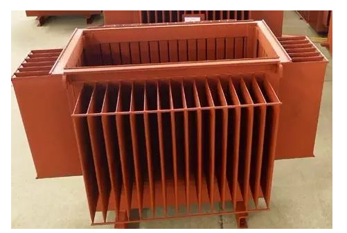
(8) Radiator
The form of the radiator is corrugated, fan-shaped, circular, exhaust pipe, etc. The larger the heat dissipation area, the better the heat dissipation effect. When there is a temperature difference between the oil temperature of the upper layer of the transformer and the oil temperature of the lower layer, the convection of the oil is formed through the radiator, and it flows back to the oil tank after cooling by the radiator, which reduces the temperature of the transformer. In order to improve the cooling effect of the transformer, measures such as air cooling, forced oil air cooling and forced oil water cooling can be adopted. The main failure of the radiator is the oil leak.
(9) Buchholz gas relay
Install the Buchholz relay between the oil conservator and the connecting pipe of the transformer tank cover by using the flange. During operation, the Buchholz relay is full of oil. When a slight fault occurs inside the transformer and bubbles are generated, they will first gather in the upper space of the Buchholz relay. And force the oil level to drop, so that the upper opening cup loses buoyancy and its own weight increases, so as to deflect in the opposite direction, making the magnet move closer to the reed switch. The principle of the lower contact baffle type is the same.
(10) Temperature measuring device
The oil surface temperature rise refers to the value that the oil surface temperature in the oil tank is allowed to exceed the ambient temperature when the transformer is working under the rated state.
The oil temperature of the main transformer body is temporarily set to alarm at 80°C and trip at 100°C.
(11) Neutral grounding knife
The neutral point grounding method of my country's 110kV power system mainly adopts the neutral point direct grounding method (including the neutral point grounding method through a small resistance), that is, a large grounding current system. Because the system has a large ground short-circuit current when a single-phase ground fault occurs.
When the transformer is powered off, its neutral point must be grounded. Because the transformer winding is semi-insulated (also known as graded insulation), that is, the main insulation of the near-neutral part of the transformer winding, its insulation level is lower than the insulation level of the winding end. Therefore, in order to prevent overvoltage damage to the transformer, the neutral point must be grounded when the transformer is powered off.
(12) Tap changer (also known as switcher)
When the oil conservator is used for the on-load voltage regulating transformer, a switch oil conservator without capsules is installed at the bottom of the oil conservator.
Transformer voltage regulation methods are divided into two types: on-load voltage regulation and no-load voltage regulation:
On-load voltage regulation means that the transformer can adjust its tap position during operation, thereby changing the transformer transformation ratio to achieve the purpose of voltage regulation.
Transformer taps are generally tapped from the high-voltage side, which mainly considers:
(1) The high-voltage winding of the transformer is generally on the outside, and the tap is easy to connect;
(2) The current on the high-voltage side is smaller, and the conductor cross-section of the lead wire and the current-carrying part of the split switch is smaller, and the influence of poor contact can be easily solved.
In principle, the tap can be on either side, and economic and technical comparisons are required. For example, the tap of a 500kV large step-down transformer is drawn from the 220kV side, while the 500kV side is fixed.
When the voltage is too low or too high, and it is necessary to adjust several taps of the on-load tap-changer to meet the requirements, it is necessary to pay attention to the situation:
It should be adjusted one gear at a time, that is, every time the N+1 or N-1 button is pressed, it will pause for 1 minute in the middle, and when a new number appears on the gear indicator, press the button again. Repeat the above process in turn until the final goal is reached. When the electric operation is linked (that is, one operation, more than one tap will be adjusted, commonly known as sliding), the second tap position should appear on the gear indicator of the main transformer control screen, and immediately press the emergency button. Stop button and change to manual operation.
(13) Oil purifier (also known as temperature difference filter)
The oil purifier is a container filled with adsorbent (silica gel or activated alumina), which is installed on the side wall of the transformer tank or the lower part of the strong oil cooler. When the transformer is running, due to the temperature difference between the upper and lower oil layers, the transformer oil passes through the oil purifier from top to bottom to form convection. When the oil is in contact with the adsorbent, the moisture, acids and oxides in it are absorbed, making the oil clean and prolonging the service life of the oil.
Oil system of oil immersed transformer
Oil-immersed transformers have several independent oil systems that are isolated from each other. When the oil-immersed transformer is in operation, the oil in these independent oil systems is not connected with each other, and the oil quality and operating conditions are also different.
(1) Main body internal oil system
The oil systems that communicate with the oil around the windings are all systems in the main body, including the oil in the cooler or radiator, the oil in the oil conservator, and the oil in the oil-filled bushing for 35kV and below.
When filling oil, the gas bleed plugs stored in the oil system must be released. Generally speaking, the above components should have their own bleed plugs. The oil in the main body mainly plays the role of insulation and cooling. Oil also increases the electrical strength of insulating paper or insulating cardboard. During vacuum oil filling, if some parts cannot withstand the same vacuum strength as the main oil tank, temporary gate isolation, such as the gate valve between the oil conservator and the main oil tank, should be used. The head of the submersible oil pump on the cooler should be enough to avoid inhalation of air due to negative pressure. This oil system must have a pressure relief device protection system to remove the pressure generated when the body is faulty.
(2) Oil in the diverter switch compartment of the on-load tap-changer
This part of the oil has its own protection system, namely flow relay, oil conservator, pressure relief valve. The oil in this switch room acts as insulation and extinguishes the current. The oil will go into the oil generated when the diverter switch cuts off the load current. This oil system needs good sealing performance, and the sealing performance must be protected even if arc pressure is generated during the switching process.
Although the oil in the diverter switch chamber of the on-load tap-changer is isolated from the oil in the main body, in order to avoid damaging the seal of the diverter switch chamber during vacuum oil filling, it should be vacuum oiled at the same time as the oil in the main body. The system has the same vacuum level, if necessary, the oil conservator of this system should also be isolated when evacuating. For the convenience of structure, the oil storage tank of the main body and the oil storage tank of the switch room are designed as a whole isolated from each other.
(3) Fully sealed for voltage levels of 60kV and above
The main function of this oil system is to insulate, or to increase the electrical strength of the insulating paper in the oil capacitor bushing. When oil is injected into the main body, the terminal at the end of the sleeve should be sealed well to avoid air intake.
picture
(4) Oil in the high pressure outlet box, or oil in the gas outlet box
The high-voltage outgoing line of the three-phase 500kV transformer is isolated through the corrugated insulation oil system. This oil system mainly acts as insulation.
In order to simplify the structure, this oil system can also be connected with the oil system in the main body through a connecting pipe or designed as a separate oil system.
(5) Various insulation tests are performed on oil-immersed transformers
The first is bleed, which releases potentially stored gas through a bleed plug. The presence or absence of potential failures can be predicted by analyzing the gas-in-oil chromatographic analysis of each system. Each oil system must meet the requirements of operation, such as absorbing the change of oil volume when the oil expands and contracts, the valve for oil discharge, the air plug, the isolation valve of the cooler and the radiator and the main oil tank, etc. Each oil system has good sealing performance. The oil in the on-load tap-changer diverter switch room should be replaced separately without releasing the oil in the main body. The oil in the main body can be released and filled with dry nitrogen during transportation.
Fault Analysis of Oil-immersed Transformer
Common faults of transformers in operation include faults of windings, bushings, tap-changers, iron cores, oil tanks and other accessories.
(1) Winding failure
There are mainly inter-turn short circuit, winding grounding, inter-phase short circuit, wire breakage and joint welding.
(2) Casing failure
The transformer bushing is fouled, causing pollution flashover in heavy fog or light rain, which makes the single-phase grounding or phase-to-phase short-circuit on the high-voltage side of the transformer.
(3) Serious leakage
The oil leakage of the transformer is serious or continuously overflows from the damaged place, so that the oil level gauge can no longer see the oil level. At this time, the transformer should be stopped immediately to repair the leakage and refuel. The reason for the oil leakage of the transformer is the welding seam cracking or sealing The parts fail, and the fuel tank is severely rusted and damaged by vibration and external force during operation.
(4) Tap changer failure
Common faults include poor contact or inaccurate position of the tap changer, melting and burns on the contact surface, and discharge of the interphase contacts or discharge of each tap.
(5) Failure due to overvoltage
When a transformer in operation is struck by lightning, due to the high potential of lightning, it will cause overvoltage outside the transformer. When some parameters of the power system change, due to electromagnetic oscillation, it will cause overvoltage inside the transformer. Most of the transformer damage caused by overvoltage is the breakdown of the main insulation of the winding, resulting in transformer failure.
(6) Failure of the iron core
The failure of the iron core is mostly caused by the insulation damage of the through-core screw of the iron core column or the clamping screw of the iron core.
(7) Oil leakage phenomenon
If the oil level of the transformer oil is too low, the bushing leads and the tap changer are exposed to the air, and the insulation level will be greatly reduced, so it is easy to cause breakdown discharge.
Transformer operation and maintenance
In order to ensure the safe operation and reliable power supply of the transformer, when an abnormal situation occurs in the transformer, it can be discovered in time, dealt with in time, and eliminate the fault in the bud to prevent the occurrence and expansion of the accident. Therefore, the transformer in operation must be checked regularly. and make a running record.
(1) The normal operation mode of the transformer
① Rated operation mode
Under the specified cooling conditions, the transformer can operate according to the specifications on the nameplate. The allowable temperature of the oil-immersed transformer during operation should be checked according to the upper oil temperature. The upper oil temperature should comply with the manufacturer's regulations, but the maximum should not exceed 95 ℃. In order to prevent the transformer oil from deteriorating too quickly, the upper oil temperature should not exceed 85℃ frequently.
The applied voltage of the transformer shall generally not exceed 105% of the rated value. At this time, the secondary side of the transformer can carry the rated current. In individual cases, the applied voltage may be 110% of the rated voltage after tests or with the agreement of the manufacturer.
② Allow overload
Transformers can operate under normal overload or accident overload conditions. The normal overload can be used frequently, and its allowable value is determined according to the load curve of the transformer, the cooling conditions and the load carried by the transformer before the overload. Accident overloads are only permitted in accident situations (transformers that are still operational).
The allowable value of accidental overload shall comply with the regulations of the manufacturer; if there is no regulation of the manufacturer, the self-cooling oil-immersed transformer can be operated according to the requirements in the table below.
(2) Abnormal operation and emergency treatment of transformers
(a) Abnormal phenomenon in operation. If any abnormal phenomenon is found in the operation of the transformer (such as oil leakage, insufficient oil level in the oil pillow, abnormal heating, abnormal sound, etc.), try to eliminate it. If one of the following situations occurs, stop immediately for repairs.
① The internal sound is loud, uneven, and there is a popping sound.
② Under normal cooling conditions, the temperature is abnormal and keeps rising.
③ The oil pillow or explosion-proof pipe injection.
④ Oil leakage causes the oil level to drop below the limit on the oil level indicator.
⑤ The color of the oil changes too much, and there is carbon in the oil.
⑥ The casing has serious damage and discharge.
(b) Impermissible overloads, abnormal temperature rises and oil levels. If the overload of the transformer exceeds the allowable value, the load of the transformer should be adjusted in time. When the rise of transformer oil temperature exceeds the allowable limit, the cause should be identified and measures should be taken to reduce it. Therefore, the following work must be carried out.
① Check the load of the transformer and the temperature of the cooling medium, and check with the temperature that should be under such load and cooling temperature.
② Check the thermometer.
③ Check the ventilation of the transformer mechanical cooling device or the transformer room.
If it is found that the oil temperature is more than 10°C higher than usual under the same load and cooling temperature, or the load remains unchanged, the oil temperature continues to rise, and the cooling device, the ventilation of the transformer room and the thermometer are all normal, it may be an internal fault of the transformer (such as Iron core fire, short circuit between coil layers, etc.), stop immediately for repair.
If the oil of the transformer has solidified, it is allowed to put the transformer into operation with load, but it is necessary to pay attention to whether the upper oil temperature and oil circulation are normal.
When it is found that the oil level of the transformer is significantly lower than the oil level of the oil temperature at that time, it should be refueled immediately. If the oil level drops rapidly due to a large amount of oil leakage, it is forbidden to change the gas relay to only act on the signal, but must take measures to stop the leakage and refuel immediately.
(c) Processing when the Buchholz relay operates. When the signal of the gas relay is activated, the transformer should be checked to find out the cause of the signal action, whether it is due to air intrusion into the transformer, or due to a decrease in oil level, or a secondary circuit failure. If the fault cannot be detected outside the transformer, it is necessary to identify the nature of the gas accumulated in the relay. If the gas is colorless, odorless and non-flammable, it is the air separated from the oil, and the transformer can continue to operate. If the gas is flammable, the transformer must be stopped and the cause of the action must be carefully studied.
When checking whether the gas is flammable, special care must be taken not to place the fire near the top of the relay, but 5-6cm above it.
If the action of the Buchholz relay is not caused by the intrusion of air into the transformer, the flash point of the oil should be checked. If the flash point is lower than the previous record by more than 5°C, it means that there is a fault in the transformer.
If the transformer trips due to the action of the gas relay, and the inspection proves that it is a flammable gas, the transformer shall not be put into operation again without special inspection and testing.
According to the nature of the fault, there are generally two types of actions of the gas relay: one is the signal action without tripping; the other is the simultaneous action of the two.
The signal action without tripping usually has the following reasons.
① Air enters the transformer due to oil leakage, refueling or poor cooling system.
② The oil level drops slowly due to temperature drop or oil leakage.
③ A small amount of gas is generated due to transformer failure.
④ Caused by traversing short circuit.
The signal and the switch act at the same time, or only the switch acts, which may be due to a serious fault inside the transformer, the oil level drops too fast, or the secondary circuit of the protection device is faulty. In some cases, such as after a repair, the air in the oil separates out too quickly and can also trip the switch.
(d) Transformer oil leakage treatment
There are two types of oil leakage: weld oil leakage and seal oil leakage. The oil leakage treatment of the welding seam is repair welding. When welding, the body should be lifted out and the oil should be drained. The cause of the oil leakage of the seal should be identified, such as poor operation (the sealing gasket is not placed correctly, the pressure is uneven, the pressure is not enough, etc.), and it should be repaired as appropriate. If the gasket is aged or damaged (such as the oil-resistant rubber is sticky, loses elasticity, cracks, etc.), the sealing material should be replaced.
(3) Patrol inspection of oil-immersed transformers
The transformers in operation should be regularly inspected and monitored in order to detect abnormal phenomena or faults in time and avoid serious accidents.
Items that should be checked and monitored generally include:
(1) Whether the transformer has abnormal sound, such as uneven sound or discharge sound.
(2) Whether the oil level is normal and whether there is leakage or oil leakage.
(3) Whether the oil temperature is normal (the upper oil temperature should not exceed 85℃ in general).
(4) Whether the casing is clean, whether there are cracks, damage and discharge.
(5) Whether the joint is hot or not.
(6) Whether the explosion-proof membrane of the explosion-proof pipe is complete.
(7) Check whether the Buchholz relay leaks oil and whether the inside is full of oil.
(8) Whether the respirator is unblocked, whether the oil level of the oil-sealed respirator is normal, and whether the silica gel in the respirator is saturated with moisture.
(9) Whether the cooling system is operating normally.
(10) Whether the ground wire of the casing is in good condition.

